This article aims at helping beginner pilots to mechanically setup a CP head.
Parts:
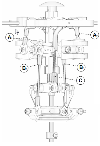
Linkage A / B / C – as shown in the figure
Linkage D – Linkage between CCPM servos and swashplate
Pitch Slider – slider between swashplate and hub
Timing pin – The pin that keep the pitch slider sync with hub
…
This article aims at helping beginner pilots to mechanically setup a CP head.
Parts: Linkage A / B / C – as shown in the figure
Linkage D – Linkage between CCPM servos and swashplate
Pitch Slider – slider between swashplate and hub
Timing pin – The pin that keep the pitch slider sync…
This article aims at helping beginner pilots to mechanically setup a CP head.
Parts: Linkage A / B / C – as shown in the figure
Linkage D – Linkage between CCPM servos and swashplate
Pitch Slider – slider between swashplate and hub
Timing pin – The pin that keep the pitch slider…
This article aims at helping beginner pilots to mechanically setup a CP head.
Parts: Linkage A / B / C – as shown in the figure
Linkage D – Linkage between CCPM servos and swashplate
Pitch Slider – slider between swashplate and hub
Timing pin – The pin that keep the pitch slider sync…
This article aims at helping beginner pilots to mechanically setup a CP head.
Parts: Linkage A / B / C – as shown in the figure
Linkage D – Linkage between CCPM servos and swashplate
Pitch Slider – slider between swashplate and hub
Timing pin – The pin that keep the pitch slider sync…
This article aims at helping beginner pilots to mechanically setup a CP head.
Parts:Linkage A / B / C – as shown in the figure
Linkage D – Linkage between CCPM servos and swashplate
Pitch Slider – slider between swashplate and hub
Timing pin – The pin that keep the pitch slider sync with hub
Mixer PS – Mixer arm…
Fig.1
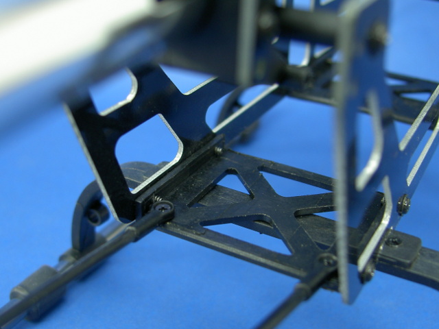
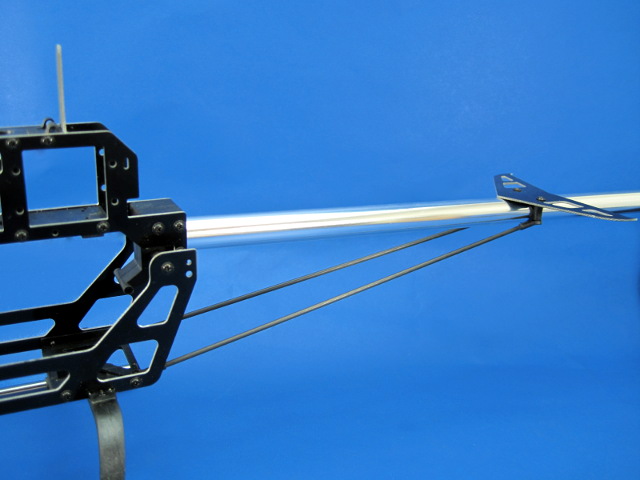
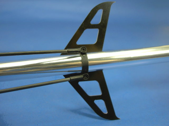
GS3-2423 Tail Boom Support can further reinforce the structure of tail boom and fiber frame. With the support of 2 x 2mm Carbon Fiber force, viberation from tail can be damped away, which gives a more solid rudder to the whole helicopter.
Fig.1
Fig.2
Figure 3 shows the installation on Neon Series Fiber Frame, the…
Fig.1
GS3-2423 Tail Boom Support can further reinforce the structure of tail boom and fiber frame. With the support of 2 x 2mm Carbon Fiber force, viberation from tail can be damped away, which gives a more solid rudder to the whole helicopter.
Fig.1
Fig.2
Figure 3 shows the installation on Neon Series Fiber Frame, the…
GS3-2423 Tail Boom Support can further reinforce the structure of tail boom and fiber frame. With the support of 2 x 2mm Carbon Fiber force, viberation from tail can be damped away, which gives a more solid rudder to the whole helicopter.
Fig.1
Fig.2
Figure 3 shows the installation on Neon Series Fiber Frame, the whole…
GS3-2423 Tail Boom Support can further reinforce the structure of tail boom and fiber frame. With the support of 2 x 2mm Carbon Fiber force, viberation from tail can be damped away, which gives a more solid rudder to the whole helicopter.
Fig.1
Fig.2
Figure 3 shows the installation on Neon Series Fiber Frame, the whole installation process…
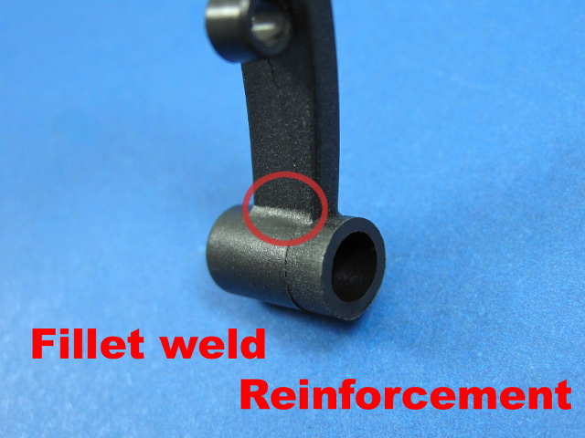
We have established a new version of landing skid, a fillet weld is added into the design to reinforce the whole structure of the skid.
The landind skid is now become more durable and take a less chance to break during hard landing or crash
We have established a new version of landing skid, a fillet weld is added into the design to reinforce the whole structure of the skid (fig. 1).
The landind skid is now become more durable and take a less chance to break during hard landing or crash
We have established a new version of landing skid, a fillet weld is added into the design to reinforce the whole structure of the skid (fig. 1).
The landind skid is now become more durable and take a less chance to break during hard landing or crash
Fig.1
Some pilots find that it is hard to insert the screws to the parts, which they easily slip away. Here is a tip. Take the mixer arm as an example. Decide which hole you are going to use. Also which side you wish to secure the ball (The…
Fig.1
Some pilots find that it is hard to insert the screws to the parts, which they easily slip away. Here is a tip. Take the mixer arm as an example. Decide which hole you are going to use. Also which side you wish to secure the ball (The mixer…
Fig.1
Some pilots find that it is hard to insert the screws to the parts, which they easily slip away. Here is a tip. Take the mixer arm as an example. Decide which hole you are going to use. Also which side you wish to secure the ball (The mixer…
Fig.1
Some pilots find that it is hard to insert the screws to the parts, which they easily slip away. Here is a tip. Take the mixer arm as an example. Decide which hole you are going to use. Also which side you wish to secure the ball (The mixer…
Fig.1
Some pilots find that it is hard to insert the screws to the parts, which they easily slip away. Here is a tip. Take the mixer arm as an example. Decide which hole you are going to use. Also which side you wish to secure the ball (The mixer…
Fig.1
Some pilots find that it is hard to insert the screws to the parts, which they easily slip away. Here is a tip. Take the mixer arm as an example. Decide which hole you are going to use. Also which side you wish to secure the ball (The mixer…
Fig.1
Some pilots find that it is hard to insert the screws to the parts, which they easily slip away. Here is a tip. Take the mixer arm as an example. Decide which hole you are going to use. Also which side you wish to secure the ball (The mixer…
Fig.1
Some pilots find that it is hard to insert the screws to the parts, which they easily slip away. Here is a tip. Take the mixer arm as an example. Decide which hole you are going to use. Also which side you wish to secure the ball (The mixer…
Fig.1
Some pilots find that it is hard to insert the screws to the parts, which they easily slip away. Here is a tip. Take the mixer arm as an example. Decide which hole you are going to use. Also which side you wish to secure the ball (The mixer…
Fig.1
Some pilots find that it is hard to insert the screws to the parts, which they easily slip away. Here is a tip. Take the mixer arm as an example. Decide which hole you are going to use. Also which side you wish to secure the ball (The mixer…
Fig.1
Some pilots find that it is hard to insert the screws to the parts, which they easily slip away. Here is a tip. Take the mixer arm as an example. Decide which hole you are going to use. Also which side you wish to secure the ball (The mixer…
Fig.1
Some pilots find that it is hard to insert the screws to the parts, which they easily slip away. Here is a tip. Take the mixer arm as an example. Decide which hole you are going to use. Also which side you wish to secure the ball (The mixer…

